
There is a very small AM modulation component. Most of the early devices that used this circuit were sold as kits, a market that was and still is very cost sensitive.
3 transistor fm transmitter with coil on circuit board plus#
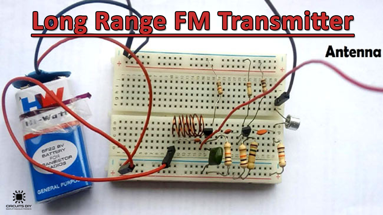
Darlington amps were built from discretes so in addition to two transistors and half a dozen resistors plus caps, the comparatively low cost dynamic microphone won out in the intro years. Even the fading germanium transistors were still around $2.50 each ($13.00 today). In the late 60's and early 70's when these were gaining traction the cost of transistors was significantly more than today. The crystal microphone was low cost but was hampered by it sensitivity to humidity so many of these devices were sold with dynamic microphones. At the time (1970) electret microphones were budget busters, often 10 X more than the dynamic microphone. Dynamic microphones produce significantly more voltage than many crystal and electret microphones. It is both device (transistor) dependent and also audio source dependent.ĭynamic microphones were the 800 pound gorilla in the late 1960s and early 70's when these appeared. Since the base emitter junction capacitance can vary from production run to production run and from manufacturer to manufacturer it is best to use the same manufacturer that the original author used. The circuits displayed are depending on the very small capacitance change the low level mike audio can create to minimize distortion. However if distortion less than 5% is the goal then you need a circuit that is much more stable than this design. The frequency is tuned by compressing or spreading the windings of the coil to vary its self inductance and distributed capacitance. My guess is the microphone is a crystal mike with low output. As you are driving the base emitter junction with audio frequencies little of the audio is shunted to ground by the 0.01 uF cap given the audio low frequency and the caps relatively high reactance. The junction capacitance will vary just enough to cause reactance modulation of the oscillator. The designer depended on the base emitter junction to act sort of like a varactor diode (voltage variable capacitance diode). L1 in parallel with the 36 pF cap determine the oscillator frequency. The current from the collector to the emitter is in phase. The 6.8 pF feeds a small amount of the rf to the emitter to sustain oscillation. The cap divider makes me think the design is based on a Colpitts topology. The base is grounded at RF by the 0.01 uF cap. FM transmitters are used to reduce noise in certain places.The device is used in a Common Base Mode.FM transmitter circuits are used in wireless sound systems in vehicles and offices.Then, the modulated signal is transmitted or radiated as radio waves at a frequency in the FM frequency range. The main purpose of the variable capacitor is to change the resonance frequency to obtain the best FM signal band. The audio signal obtained from the microphone passes through the base of the transistor to modulate the output signal of the LC circuit in the form of FM. The transmitter circuit stores energy for oscillation as it is obtained from LC circuits. When current is passed through L1 Inductor and the variable capacitor, the FM Transmitter Circuit will start oscillating with the resonant frequency of the carrier signal. The oscillation circuit consists of the transistor (2N3904), inductor, and variable capacitor.

The oscillator is required to generate carrier waves in the FM transmitter.

The air pressure around the mic produces such capacitance. The microphone is assumed to catch the sound signals and there is the presence of a sensor with a capacitance value inside it. The circuit diagram is shown for the FM transmitter.


 0 kommentar(er)
